Choosing a cnc engraving machine for metal is less about headline wattage and more about matching the machine to the work. A nameplate may promise speed, yet thin aluminum can chatter if the frame lacks rigidity. Stainless steel demands a different balance of spindle performance, tooling, feed rate, and chip control. The cut tells the truth.
The 2019 Deloitte and MAPI Smart Factory Study found that 86% of surveyed manufacturing executives expected smart factory solutions to strengthen competitiveness within five years. That finding concerns manufacturing broadly, not engraving machines specifically. Still, it highlights why measurable performance matters: repeatability, setup time, maintenance needs, and operator skill can shape real production costs. Quality expert W. Edwards Deming’s often-cited reminder, “Without data, you’re just another person with an opinion,” offers a useful lens for comparing machines. Ask suppliers for sample engravings on your actual alloy, with your intended line width and depth.
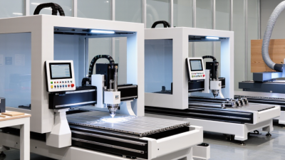
Look closely at the result. Are edges clean? Is the depth consistent across the plate? Check the work envelope, clamping options, controller, compatible tooling, and service support before comparing price. A machine suited to nameplates may struggle with deeper relief work or long production runs. Test before buying.
There is no universal best choice. A modest machine may be right for occasional marks, while a rigid, well-supported system may suit daily production. One detail is easy to overlook: a polished demonstration sample cannot reveal every maintenance burden. Use verified specifications, practical trials, and a clear list of your materials and tolerances to guide the decision.
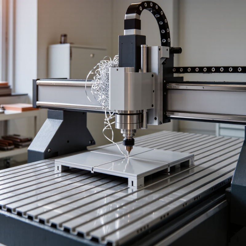
Before choosing a CNC engraving machine for metal, define what the finished mark must do. A serial number that only needs to remain visible may require surface marking, not a deep groove. For shallow engraving, specify the line width and depth, such as a fine 0.2-millimeter channel on an aluminum panel. Depth affects cutting time and tool wear. That distinction matters.
Deep cutting removes more material and demands a rigid frame, controlled spindle speed, and secure workholding. A thin plate can vibrate under the cutter, leaving rough edges or uneven lettering. Check whether the machine can maintain the required depth across your actual workpiece, not just a sample coupon. Bring the same alloy and thickness you plan to process. Ask for a test cut, then inspect the smallest text, edge quality, and burrs under good light. One detail is easy to miss: tool diameter limits how tightly the machine can cut inside corners. Coolant or chip removal may also matter, depending on the material and cutting method. No specification sheet replaces a real test. I would allow time for one imperfect trial; it can reveal a setup issue before it becomes a production problem.
A 20–100 W fiber laser suits fine, repeatable marks on stainless steel, aluminum, and coated parts. Its near-infrared wavelength is typically around 1.06 μm, a key figure in industrial fiber-laser specifications (Fraunhofer ILT, laser materials-processing technical data). Lower power can handle serial numbers and shallow surface marks; higher power may improve speed or depth, depending on alloy, finish, and focus. Shiny metal can reflect energy, so test the exact surface before choosing. Small details matter.
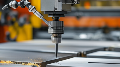
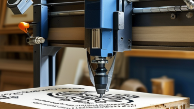
A rotary CNC engraver uses a rotating cutter, making it a practical choice for physical grooves, lettering, and deeper cuts. Cutter shape, spindle speed, and feed rate affect edge quality and tool wear. The ASM Handbook’s machining guidance emphasizes how material properties and cutting conditions influence tool performance. In practice, a steel coupon can reveal burrs that a screen preview cannot.
Compare the real job, not just rated watts. Ask for sample marks on your own metal, then inspect line width, depth, cycle time, and heat discoloration. Fiber lasers avoid cutter contact, but their settings still need careful tuning. Rotary systems create chips and need secure clamping. A slight imperfection: setup time can outweigh the marked cycle time on short runs. Test the actual alloy.
Typical rated power ranges (watts)
Fiber laser engravers in the 20–100 W class are rated by optical laser output. Benchtop rotary CNC engravers commonly use spindle motors in roughly the 100–1,000 W range. These ratings describe different things and are not directly comparable: laser marking is generally suited to fast surface marking, while a rotary CNC can physically cut metal when paired with suitable tooling and a rigid setup. Actual capabilities vary by machine, material, and process.
When choosing a CNC engraving machine for metal, match spindle speed and tooling to the workpiece’s hardness—not just its appearance. ISO 513:2012 classifies work materials into machining groups, while ASM Handbook, Volume 16, discusses how material properties affect cutting. Harder alloys generally need tougher cutting edges and more conservative cutting speeds. Softer aluminum can often tolerate sharper tools and higher speeds, but a tiny engraving cutter still needs careful chip control. Small details matter.
Use the cutter diameter to convert cutting speed into spindle speed:
For example, a 6 mm cutter at 60 m/min runs at about 3,180 rpm. Treat that as a calculation, not a universal setting. A machine may lack the torque or rigidity to cut cleanly at that speed. Check the tool maker’s cutting data, then test on scrap. Watch for a polished, rubbing edge, squeal, or heat discoloration; these can signal an unsuitable speed, feed, or tool. I would not assume hardness alone predicts the result. Tool geometry, coating, stick-out, and machine vibration can change it—and first-pass settings are often imperfect.
When choosing a CNC engraving machine for metal, do not rely on a resolution figure alone. Check whether the supplier can provide positioning test results based on ISO 230-2. This standard describes methods for assessing the positioning accuracy and repeatability of numerically controlled machine axes. A calibrated laser interferometer may measure commanded movement against actual travel. Small differences matter.
Ask for results in both travel directions, not only a single forward run. The report should identify the tested axis, measurement positions, ambient conditions, and measurement equipment. Bidirectional data can reveal reversal errors when an axis changes direction. For example, a machine may reach a point consistently from the left but shift slightly when approaching from the right. That shift can affect fine lettering or closely spaced features. Check the full report, not just its best number.
A careful test also needs stable conditions. Temperature changes, machine warm-up, and setup can influence measured movement. Compare machines only when their test conditions are clear and reasonably comparable. I would not treat one clean chart as proof of engraving quality. ISO 230-2 evaluates axis positioning; it does not account for every factor, such as tool wear, workholding, or metal response. Ask how the machine performs after warm-up, and consider verifying a sample cut on your own material. One test is never the whole story.
Use this comparison guide to evaluate machine requirements and test evidence. Any numerical acceptance values below are illustrative buyer targets—not ISO 230-2 limits or measured results for a specific machine. Actual performance must be confirmed with a documented test.
| Selection Dimension | What to Check | Illustrative Requirement or Data | How to Verify | Why It Matters for Metal Engraving |
|---|---|---|---|---|
| Positioning accuracy | Axis positioning deviation across the working travel, reported separately for each tested axis. | Example project target: maximum absolute positioning deviation of 0.020 mm over the specified test travel. This is a buyer-defined target, not a universal machine specification. | Request an ISO 230-2 test report identifying the axis, travel, test positions, direction of approach, measuring equipment, and reported deviations. | Accurate positioning helps maintain feature location and spacing, especially when engraving multiple parts or working near edges. |
| Positioning repeatability | Variation when an axis returns to the same commanded positions, including results from both approach directions where reported. | Example project target: repeatability within 0.010 mm at the selected test positions. Confirm that the report defines the statistic and test conditions. | Compare repeated measurements at the same commanded positions in the ISO 230-2 report; do not rely only on a general brochure figure. | Consistent positioning supports repeatable engraving depth, alignment, and part-to-part results. |
| Test coverage and axis travel | Whether the test covers the axis travel and work area needed for the intended parts. | Specify the required usable X, Y, and Z travel in millimetres before comparing machines. An accuracy result applies to its stated test conditions and range. | Check that the report states the tested range and positions. Ask for additional evidence if the report covers only part of the required working area. | A machine’s performance at one location does not by itself establish performance throughout its full working envelope. |
| Bidirectional measurement | Measurements made while approaching test positions from opposite directions, when included in the test plan. | Look for clearly identified positive- and negative-direction results and any reported reversal or backlash-related effects. | Review the test procedure and raw or summarized results to confirm that approach direction is documented. | Direction-dependent errors can affect contours and small features when toolpaths reverse direction. |
| Measurement equipment | Instrument type, calibration status, setup, and measurement uncertainty. | Ask for the instrument identification and valid calibration information. The report should state enough detail to judge whether the measurement supports the claimed result. | Request the calibration certificate or traceability details and the measurement uncertainty stated by the test provider. | Positioning figures are meaningful only when the measurement method and its uncertainty are adequately documented. |
| Thermal and environmental conditions | Machine warm-up, ambient temperature, and other conditions recorded during the test. | Compare test conditions with the intended production environment; temperature and machine operating state should be documented. | Check the report for warm-up and environmental notes. Ask whether the machine was tested under conditions representative of normal operation. | Thermal changes can affect machine geometry and therefore the repeatability of fine engraving work. |
| Workholding and machine stability | Rigidity of the frame, spindle support, table, and workholding arrangement for the planned material and part size. | Define the largest workpiece, fixture arrangement, and typical engraving operation as part of the application review. | Request a sample cut or engraving trial using representative material, tooling, fixture, and feature size. | Axis positioning accuracy alone does not guarantee a clean result if vibration, deflection, or insecure workholding affects the cut. |
| Spindle and tool suitability | Spindle speed range, collet or tool interface, runout data, and compatibility with the intended engraving tools. | Match the spindle and tool setup to the material and feature size; request runout data at the tool or collet where available. | Verify specifications and evaluate a representative cutting test. Confirm the measurement location and method for any runout figure. | Tool runout and unsuitable cutting conditions can widen fine lines or produce inconsistent engraving, even when axis positioning is accurate. |
| Acceptance test and reporting | A written acceptance plan with defined axes, positions, tolerances, test conditions, and report requirements. | Set project-specific limits before purchase. Example: require an agreed ISO 230-2 test report for the axes and travel relevant to the job. | Include the test scope, pass/fail criteria, measurement records, and any agreed remedy in the purchase or acceptance documentation. | Clear criteria make supplier comparisons more meaningful and reduce ambiguity about what a quoted accuracy value represents. |
When choosing a CNC engraving machine for metal, check its laser safety classification before comparing speed or spot size. IEC 60825-1 classifies laser products according to accessible emission, not simply the source’s advertised power. Ask for documentation covering the exact machine configuration, including its enclosure, viewing window, and operating modes. A label alone is not proof. The manual and test records should identify the classification and explain safe operation.
Look closely at access points. Can the lid open during engraving? Are interlocks fitted and tested? Does the viewing window suit the laser’s wavelength? These details matter in a real workshop, where a misaligned panel or bypassed interlock can change exposure risks. For an enclosed machine, confirm its classification during normal use and learn what happens in setup or maintenance modes. “Class 1” on the outside may not describe every service condition. That distinction is easy to overlook. Ask how operators should respond to faults, and verify that local safety procedures match the documentation. I would not rely on a sales sheet alone; paperwork can be incomplete, and it is worth asking specific follow-up questions.
Arsun Engineers is the well-known manufacturer, exporter, and supplier of highly operational machines.