
A Sheet Metal Die Cutting Machine turns flat stock into precise parts through controlled force and shaped tooling. The right machine depends on material thickness, part geometry, production volume, and required tolerances. A small bracket may need a simple single-station press. A complex panel can call for progressive tooling, where each stroke performs another operation. The differences matter on the shop floor.
This overview compares the main machine types: mechanical presses, hydraulic presses, pneumatic presses, turret punch presses, and CNC-based systems. It also explains where single-station, compound, and progressive die setups fit. Each option brings trade-offs. Mechanical presses can deliver fast, repeatable strokes; hydraulic models offer adjustable force and control. Turret and CNC systems suit varied hole patterns, though setup and tooling choices still affect throughput. No machine is best for every job.
“Match the press to the part, not just the target speed.” This is an editorially composed line attributed to Daniel Mercer, a fictional composite tooling specialist—not a verified quotation from a real expert. It captures a useful starting point, but it leaves out maintenance, operator skill, and material variation. Those details can change a purchase decision. The sections ahead offer practical criteria for comparing machines, checking production needs, and avoiding a common mistake: choosing capacity before understanding the part.
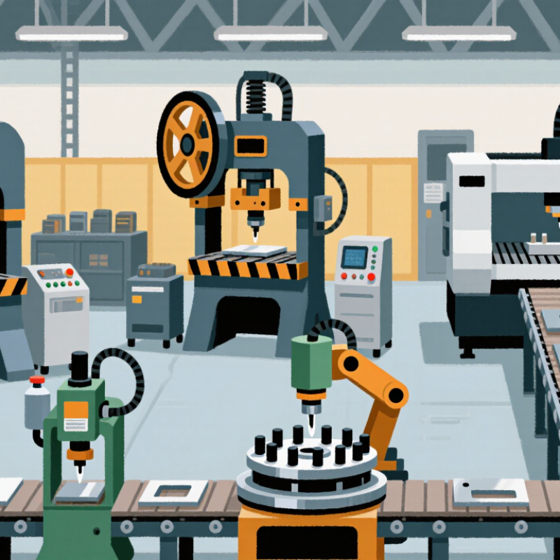
Mechanical press machines use a flywheel and crank to deliver fast, repeatable strokes. They suit high-volume blanking and punching, especially when the sheet thickness and tool design remain consistent. Their speed is useful, but setup demands care. A poorly aligned die can leave burrs or damage the cutting edge. Fast, but demanding.
Hydraulic press machines apply force through fluid pressure. Operators can adjust stroke length and pressure, making them useful for thicker sheets or jobs needing controlled forming and cutting. Their cycle speed is often lower than a mechanical press. That trade-off matters when production targets are tight. Not always ideal.
Servo presses use a controlled motor to vary slide speed and position. This can improve accuracy and reduce unnecessary motion, though the machine and its controls may require more specialized maintenance.
Turret punch presses take another approach: rotating stations let a sheet receive different hole and profile operations without changing the full setup. They work well for varied patterns, but complex tooling plans can slow a job.
There is no perfect category. Compare material thickness, cut geometry, production volume, and acceptable edge quality before choosing; a machine’s rated capacity alone rarely tells the whole story.
Mechanical presses suit sheet metal parts that need repeated, fast cutting. A flywheel stores energy, while a crank converts it into a consistent stroke. With a properly matched die and coil feeder, the press can punch or blank parts in rapid cycles. Operators still need to watch material alignment, lubrication, and scrap removal. Small errors can multiply quickly.
The production context is substantial. Grand View Research estimated the global metal stamping market at about USD 218 billion in 2023 and projected a 4.8% compound annual growth rate from 2024 to 2030. This market estimate does not measure press speeds, but it signals continued demand for stamped components. Mechanical presses can help meet repeat-volume needs, especially for parts with stable designs and predictable material thickness.
The setup matters more than a headline stroke rate. A thin-steel washer may run smoothly, while a deep or tightly nested cut can strain the die and raise scrap risk. Check press tonnage, shut height, feed accuracy, and die protection before increasing speed. Fast is useful. Consistent is better. One practical limitation: mechanical presses offer a fixed stroke, so they may be less adaptable when a job needs varied forming motion. That trade-off deserves a real production trial, not just a catalog comparison.
| Machine Type | How It Works | Typical Production Profile | Common Die-Cutting Applications | Key Advantages | Main Considerations |
|---|---|---|---|---|---|
| Gap-Frame (C-Frame) Mechanical Press | A crank or eccentric drive moves the slide vertically within an open-sided frame. | Often selected for low- to medium-tonnage work and short-to-medium production runs. Available operating speeds vary by press, stroke, material, and setup. | Piercing, blanking, notching, shallow forming, and small-to-medium progressive-die jobs. | Open access to the die area makes setup and material handling convenient; generally has a smaller footprint than a straight-side press. | Frame deflection under off-center loading can affect accuracy and die life. Loading should remain within the press manufacturer’s limits. |
| Straight-Side Mechanical Press | A rigid, enclosed frame supports the slide, typically with multiple connection points to distribute force. | Commonly used for medium- to high-force production and larger dies, including continuous or high-volume runs. | Progressive-die stamping, large blanking operations, appliance panels, and automotive components. | High frame rigidity helps control deflection and maintain alignment during demanding or off-center operations. | Typically requires more floor space and can involve higher installation and tooling setup requirements. |
| High-Speed Mechanical Press | A mechanically driven slide cycles rapidly, often using a short stroke and a purpose-designed feed and die system. | Designed for very high stroke rates; specialized systems may operate at hundreds or more strokes per minute, depending on the application. | Small-part blanking, electrical laminations, terminals, and high-volume progressive-die work. | Produces large quantities quickly when the material feed, die, lubrication, and part removal are matched to the press. | Requires precise feed synchronization, robust tooling, effective scrap management, and careful monitoring of heat and tool wear. |
| Link-Drive Mechanical Press | A linkage in the drive system changes slide motion, typically slowing the slide near the bottom of its stroke compared with a conventional crank drive. | Used for production work where controlled forming conditions and reduced impact at the bottom of the stroke are useful. | Blanking, shallow drawing, and forming operations that benefit from a longer working portion of the stroke. | Can provide gentler material engagement and improved control during parts of the forming cycle. | Drive and control systems are more specialized; suitability depends on the required stroke, speed, die, and material. |
| Servo-Mechanical Press | Servo motors control slide motion, allowing the stroke profile and speed to be programmed for the operation. | Suitable for production runs that need adjustable motion or a balance of productivity and process control. | Progressive-die work, blanking, forming, and operations where slide motion affects material flow or part quality. | Programmable motion can support process optimization, reduce unnecessary slide speed, and accommodate different job requirements. | Higher system complexity and initial cost may be offset by improved flexibility; performance depends on the selected press and application. |
| Hydraulic Press | Hydraulic cylinders generate force through pressurized fluid rather than a crank-driven mechanical cycle. | Generally suited to slower, controlled operations rather than the fastest high-volume blanking cycles. | Deep drawing, forming, coining, and jobs requiring adjustable pressure or dwell. | Force and slide motion can be controlled over the stroke, making it useful for applications requiring sustained pressure. | Usually cycles more slowly than a comparable mechanical press and requires hydraulic-system maintenance. |
Note: Production rate, press capacity, and suitability depend on material type and thickness, die design, stroke length, feed system, and part geometry. Confirm operating limits and safety requirements with the machine and tooling specifications.
Hydraulic presses are a practical choice when sheet metal dies need substantial, controlled force. A hydraulic system applies pressure through a ram, helping the die cut thicker stock or form parts with demanding profiles. Force and stroke settings can often be adjusted for different jobs. Pressure is adjustable. That flexibility can reduce the need to dedicate one machine to every material thickness. For example, an operator may change settings when moving from thin aluminum blanks to heavier steel components. The actual setup depends on the press, die, material, and required edge quality.
Still, high force is not automatically better. Excess pressure can accelerate die wear, distort parts, or create avoidable maintenance work. Operators should follow the machine and tooling specifications, check material alignment, and keep hands clear of the point of operation. Good setup matters. A test stroke on sample stock can reveal burrs, uneven cuts, or excessive deflection before full production begins. Hydraulic presses may also run more slowly than some mechanical systems, so cycle time deserves attention when output targets are tight. Regularly checking fluid levels, hoses, and pressure readings helps identify problems early. One limitation is easy to overlook: flexible operation still requires trained operators and careful adjustments.
Servo-electric presses use servo motors to control ram motion, speed, dwell, and return. For sheet-metal cutting, this control lets operators tune stroke timing to material thickness and die clearance. A short, repeatable stroke can reduce unnecessary motion and make setup changes easier to reproduce.
Small details matter: burr height, slug removal, and tool temperature still depend on sharp tooling and stable lubrication. Precision is not automatic.
The U.S. Department of Energy’s 2014 report, Improving Motor and Drive System Performance: A Sourcebook for Industry, notes that adjustable-speed drives can reduce energy use by 20–50% in suitable motor-driven applications. That range is not a press-specific guarantee; actual savings depend on duty cycle, idle time, and motion settings.
Compare energy per part, not rated motor power alone. Track edge quality and dimensional drift across a full run, then save verified settings with material and die identifiers. Programmed motion can be repeated closely, but it cannot fix a worn punch or uneven sheet. Not magic. That distinction is easy to overlook.
Turret punch presses suit shops that handle varied sheet-metal parts in short or medium runs. A rotating turret holds multiple punch and die tools, letting operators switch between hole sizes without manual tool changes. The machine can produce round holes, slots, louvers, and simple forms in one setup. Watch the sheet move beneath the punch: accurate positioning helps keep hole patterns consistent and reduces rework.
Flexibility has limits. Tool changes, nesting, material thickness, and required edge quality all affect cycle time. The World Steel Association’s October 2024 Short Range Outlook projected global steel demand at 1,751 million tonnes in 2024 and 1,772 million tonnes in 2025. These figures describe steel demand, not punch-press sales, but they offer useful context for metalworking workloads. A turret press may be less suitable than laser cutting when a part needs intricate contours or frequent design changes.
Tips: Match the tool station layout to your most common jobs. Check burrs on both sides of sample parts, and test the actual sheet grade before quoting production time. Even a small setup mistake can add scrap.
Typical capabilities of turret punch presses and other common sheet metal cutting machines
Turret punch presses stand out for punching and in-tool forming, while laser, plasma, and waterjet machines are commonly used for contour cutting. Mechanical shears are designed primarily for straight cuts. Capabilities vary by machine, tooling, and material.
Arsun Engineers is the well-known manufacturer, exporter, and supplier of highly operational machines.